Wind tunnel Laboratory
Coordinator:
Professor C. R. Chu (ext:34138)
1.Atmospheric Boundary Layer Wind Tunnel
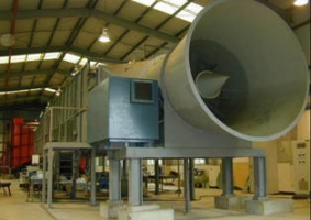
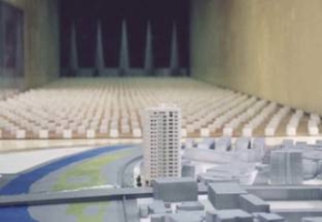
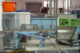
The atmospheric boundary layer wind tunnel is an open-circuit, low-speed wind tunnel designed to simulate atmospheric boundary layer flows, in which many civil engineering problems occur. For example, air pollution in the urban area, wind load on the high-rise building and suspending bridges all can be studied in this wind tunnel. Due to the fact that atmospheric boundary layer is usually much higher than the building immersed in it, the simulated boundary layer in the wind tunnel must be quite thick (the test section therefore should be large) in order for the model building to be of reasonable size.
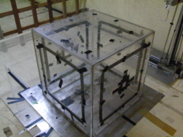
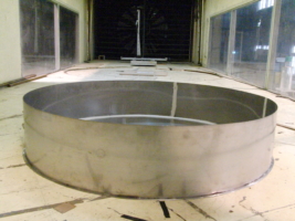
The total length of the wind tunnel is 29.2 m, test section is 18.5 m long, 3.1 m wide, and 2.1 m high. The ceiling of the test section is adjustable to Compensate for blockage when large models are used. Two turntables (diameter 2.0 m and 2.8 m) in the test section can be easily rotated to change the effective wind direction to the models. A 200 hp motor driving a 1.8 m diameter fan produces a top wind speed of 20 m/s. The 1:4 contraction section contains honeycomb and four screens to produce a low-turbulence flow at the entrance of the test section. Vorticity generators at the entrance of the test section are used to create a thick boundary layer. An instrument carriage mounted on rails can three-dimensionally position the measuring sensors by remote control. A smaller wind tunnel (1.0 m long, 0.2 m wide, and 0.2 m high) is also available for the calibration of instruments and smaller scale studies.
2.Testing of Wind Turbines
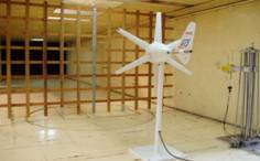
This study investigates the performance and efficiency of wind turbines in steady flow and turbulent flow. The wind speed was measured by a thermal anemometer, and output power of wind turbines was measured by a DC transformer.
3.Wind Durability Test
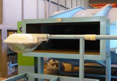
This study tests the durability of objects in high wind speed. The testing wind speed is 54 m/s (Beaufort Scale 16). The object could be installed at different attack angles. After the testing, the object will be check for any deformation, crack or failure to determine its durability in the high wind speed.
Hydraulics Laboratory
Coordinator:
Professor H. T. Chou (ext:34125)
1.Stratified Water Flume
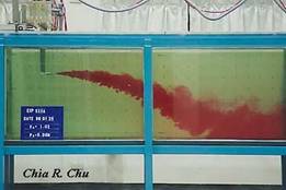
The stratified water flume is designed to study fluid flows under stratified condition. For example, internal wave, ocean outfall, dispersion in stably stratified atmosphere all can be studied in this facility. The test section of the flume is 25.0 m long, 1.0 m wide and 1.0 m deep, with glass side walls to allow for flow visualization. A filling system, consisting of a 1.0 m by 1.0 m, and 1.5 m deep mixing tank, pipe lines at the flume bottom and pump, provides the capability of filling the flume with salt water layer by layer to the required stratification condition. Both linear and two-layer stratified flows can be generated in the flume. A towing carriage on the top of the water flume provides a mounting device for model. The carriage speed is continuously adjustable from 0 to 0.8 m/s.
2.Tilting Water Flume:
The water flume is designed to study open channel flows. The test section of the flume is 8.0 long, 0.4 m wide and 0.8 m deep, with glass side walls to allow for flow visualization. The slope of the test section is continuously adjustable from 0 to 10%. The recirculation water pump is 10 hp pumps with capacity of 0.08 m3/s. A maximum Froude number of about 2.0 and Reynolds number of order 2.0×10⁵ can be attained, which permits experiments over a wide range of flow conditions.
3. Central rotor circulating water flume
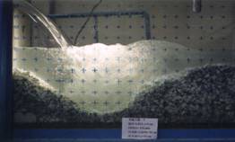
The flume is 2.8m long, 0.12m wide and 0.6m deep. The slope is adjustable, and the fluid flows out from right-hand side. The entrance of fluid is 0.8m long, supplying flows from a plane source bottom. The visual section is 2.0m long, with acrylic side walls to visualize. The bottom of the test section with a horizontal hump which connects the flow entrance by a quaternary circumference with a radius of 0.16m at right side, and at left side connecting a changeable acrylic plate with different length, and at the middle with a 0.5m long caterpillar band can CCW/CW rotate by central rotor. Besides, at the flume end with a changeable weir can control the flow depth of upstream, so which can create a river pool or estuary closing situation, with deepest depth is 0.16m.

Department of Civil Engineering at NCU
Contact Us
Tel:8863-422-7151 #34070
Fax:8863-425-2960
Mail:ncu4100@cc.ncu.edu.tw

